Autotransformer
Volume Control
The AVC-28 is
a multi tapped autotransformer made from a high-performance
100% permalloy core. Its
primary application is in so-called (transformer)
passive preamplifiers. The AVC-28 by applying
autoformer technology offers a material improvement
over all schemes based around resistive attenuation.
The
so-called passive preamplifier appeared on the
map with the emergence of the CD-player. Modern
sources generally offer output levels sufficient
to drive power amplifiers to full power (usually
2V RMS or more for digital full scale) and also
offer sufficient drive for external devices
and cables.
Many
CD-players and similar devices have output impedances
lower than 1kOhm, some are materially lower.
Whilst (resistive) passive preamplifiers initially
created notable interest as a sonically extremely
pure method of controlling volume, they have
soon faded back. These (resistive) passive preamplifiers
can sound very "pure", but they lack
dynamics. The sound becomes boring. Problem
with the resistive preamplifier is that the
attenuated portion of the signal is "thrown
away" as heat. The (resistive) volume control
can't supply enough electrons to drive the capacitance
of the interconnect.
Volume controls applying transformer technology,
don't throw away any energy. When the voltage
is transformed down, the output current is transformed
up. This current capability gives the transformer
passive preamplifier the dynamic sound of an
active preamplifier.
A
Transformer Volume Control (TVC) uses separate
primary and secondary windings. While this has
advantages (isolation between primary and secondary
windings) it can also lead to problems with
resonance's and non-flat frequency response
(especially at lower level settings). Some or
the more budget minded units show ultrasonic
peaks of more than 6dB just slightly above the
audio band, with notable impact on sound quality.
Also, as only halve the winding space can be
used for the input winding the primary inductance
is limited and hence the low frequency response
is limited.
An
Autoformer Volume Control (AVC) instead has
only one winding, used for both input and output.
As such resonance's are better controlled, any
that are present in the AVC-28 are shifted to
beyond 200KHz and are well damped. Also, as
the whole winding space is used for the input
winding a greater primary inductance can be
attained which allows a better low frequency
response with a given source than a TVC using
the same core. Additionally the better coupling
and greater number of turns allows a larger
amount of attenuation to be build in, compared
to TVC controls.
The
introduction of the autoformer volume control
AVC-28 can make passive control units that work
more effectively and in a much wider range of
environments than comparable resistive or transformer
volume controls. Considerable research and development
has resulted in the current model AVC-28 whose
specifications and measurements are covered
in this document.
The
full permalloy core can handle all line level
signals (up to around +20 dBu, 7.75V)
AVC-28
Specifications
•
Nominal Impedance:100K Ohm
• Maximum
Attenuation:60dB
• Primary
Inductance (@20Hz):1000H
• Impedance
(@1KHz):> 400K Ohm
• Maximum
Level (@20Hz):>7.75V (+20dBu)
• Frequency
Response -20dB Tap:<5Hz – > 200KHz
(+0dB/-3dB, 100R Source)
AVC-28 Technical details
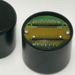
The autoformer is housed in
a soft steel shielding can that measures 60mm
in diameter and 50mm in height, excluding the
connecting pins. The threaded holes are included
to allow mounting the autoformer to a suitably
drilled metal plate.
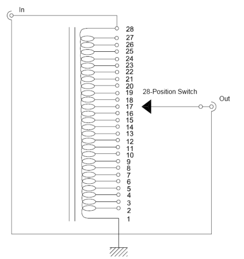
The single winding winding offers
a number of taps allowing the following attenuation
values:
0 dB, -2 dB, -4 dB, -6 dB, -8
dB, -10 dB, -12 dB, -14 dB, -16 dB, -18 dB,
-20 dB, -22 dB, -24 dB, -26 dB, -28 dB, -30
dB, -32 dB, -34 dB, -36 dB, -38 dB, -40 dB,
-42 dB, -44 dB, -48 dB, -52 dB, -56 dB, -60
dB
With these values the steps
by which the volume is changed over the majority
of the range is smaller than the commonly acknowledged
limit of audibility (3dB), giving consistent
fine control over the volume.
It is possible to achieve some
gain using this autoformer, by connecting the
input to a tap that is marked as attenuation.
In principle the gain can be very high, however
using any gain considerably increases the load
on the source and high gain produces potentially
punishingly low loads that cannot be driven
successfully by most sources.
Realistically 6 – 10dB
of Gain form the maximum for the AVC-28
The full winding has around
600 Ohm DC Winding resistance.
The primary inductive reactance
at 20 Hz is in excess of 100K Ohm (950 H Primary
Inductance) and thus provides an input impedance
of more than 100K Ohm across the audio band
if the secondary loading is infinite.
Input considerations
The input impedance of the AVC-28
is strongly dependent upon the load impedance
and selected attenuation. (Load impedance =
the input
input impedance of the power amplifier behind
the AVC-28)
The worst-case input impedance occurs with no
attenuation selected, in this case the input
impedance will equal the load impedance plus
the inductive losses. The AVC-28 should not
be used with loads lower than 10K Ohm. The use
of a 2.2uF or larger coupling capacitor in equipment
preceding the AVC-28 should suffice in all conditions.
The AVC-28 is best used with
a 1…2.2uF coupling capacitor in parallel
with an RC “snubber” of 10uF+3.3K.
In the case of operation with
6dB of gain and with a 10K Ohm load (the power
amplifier) on the output, the worst-case load
impedance on the source (the thing driving the
AVC) will be 2500 Ohm plus copper losses. This
is a very severe loading and many items of consumer
electronic will not be able to drive such a
load adequately! It is thus recommended that
the 6dB step-up connection be used only with
relatively high impedance loads (> 40kOhm),
like for example Valve Amplifiers. If the 6dB
step-up connection is to be used with a 10k
load on the output the preceding coupling capacitor
(in the thing driving the AVC) should be no
smaller than 10uF.
As soon as the signal is attenuated
(which is the way the AVC-28 will be operated
in most cases, most of the time) the input impedance
rises and is ultimately only limited by the
Inductive and Capacitive reactance of the primary
winding near the outer edges of the audio band.
In the midrange the input impedance of the AVC-28
based device can become VERY HIGH (which is
a good thing :-). With a 10K load and 14dB attenuation
selected, the midrange input impedance will
approach 250K Ohm. Hence, in the subjectively
critical midrange, the loading of the source
is drastically lowered, resulting in most cases
in lowered distortion from the source.
The limit of the input voltage
to the AVC-28 depends upon the exact frequency
and also the source impedance.
For a source impedance of 50
Ohm and the unity gain connection a maximum
level of +20dBu (7.75V RMS) is permissible above
20Hz for the AVC-28. Permissible levels change
according with gain, so with 6dB passive gain
maximum levels are 6dB lower.
The input to the AVC-28 must
be COMPLETELY free of DC offset; the presence
of DC current materially degrades the performance
of the AVC-28 Autoformer, both with respect
to level handling and frequency response. The
source impedance (= output impedance of the
source driving the AVC) in general should be
as low as possible, the lower the impedance
from which the AVC-28 is operated the lower
the distortion and the wider the effective bandwidth.
Output considerations
The output impedance of the
AVC-28 follows a fairly complex patterns but
the worst case is found with no attenuation.
In this case the source impedance and the copper
losses determine your output impedance for the
unity gain connection. Thus for a CD-Player
with 200 Ohm output impedance the worst case
output impedance after the AVC-28 is around
600 Ohm. If the AVC-28 is used with 6dB step-up
the source impedance is “stepped up”
too, namely by the square of the step-up ratio
(2*2=4), so our 200 Ohm source impedance becomes
800 Ohm, which is added to the 400 Ohm copper
losses, for a total worst case output impedance
of 1200 Ohm.
For reference, the output impedance
of the popular Audible Illusions Tube Preamp’s
line stage is 1200 Ohm. The highly reviewed
Conrad Johnson Premier 17LS line stage has around
850 Ohm output impedance.
Attenuation
(dB) |
Input
Impedance
@ 1KHz (Ohm) |
Input
Impedance
@ 20KHz (Ohm) |
Output
Impedance
@ 1KHz (Ohm) |
| |
|
|
|
| 0 |
9.75K |
9K |
1K |
| -6 |
36K |
28K |
320 |
| -12 |
114K |
58K |
94 |
| -18 |
246K |
80K |
26 |
| -24 |
346K |
88K |
6 |
| -40 |
398K |
92K |
0.2 |
The table shown illustrates
the input impedances of the AVC-28 at 1kHz and
20Hz and the output impedance in unity gain
mode when driven from a 1K Ohm source and a
with a 10K Ohm output load at different attenuation
settings. This should give some general idea
of the relevant relationships.
With
all autoformers the ultimately realized output
bandwidth is very much system and application
dependent, but the bandwidth limited AVC-28
when driven from a sufficiently low impedance
(1K Ohm or less) will provide a usable bandwidth
of at least 5Hz – 200KHz (+0/-3dB) or
better.
|